

Order Guide: How to select an encoder?
Before you determine to order a rotary encoder, here are a few questions that may help to make the best decision.
A. Do you need an incremental encoder or an absolute encoder?
B. What is the signal output and power supply voltage?
C. What resolution does the application call for?
D. How to mount this encoder and how to connect the encoder to controls?
E. What environmental and mechanical stresses does the encoder need to bear?
It’s very important for you to confirm the right encoder characteristics for your application.
NowLet's go back to each question and explore the many options you have when selecting an industrial rotary encoder.
A. Do you need an incremental encoder or an absolute encoder?
Incremental and absolute encoders can be used for speed, direction, and position.
The difference between absolute encoder and incremental encoder is :
1. The absolute encoder will retain your position after power loss and an incremental encoder will not.
The incremental encoder usually needs to perform a “homing” sequence after a power loss.
2. Incremental encoders are generally less expensive and the output needed is a square wave for counting, speed, and direction.
Absolute encoders are normally used for continuous position and possess other attributes such as speed, scaling, preset, and fieldbus functions.
B. What is the signal output and power supply voltage?
For incremental encoder output, there are open collector (NPN), PNP,push-pull, line driver.
1. The NPN Open Collector -- The NPN Open Collector(NPN) is an interface based on an output circuit with an NPN transistor.
An open collector is the unconnected collector connection of an NPN transistor, whose emitter is connected to earth and whose collector is connected to the output.
2. PNP output
The PNP output is an interface based on an output circuit with a PNP transistor.
3. Push-Pull output(HTL)
High Voltage Transistor Logic functions with a voltage supply in the range 10 and 30 V DC, with 24 V DC being the most usual.
“Low” is defined as an output of between 0 V and 3 V and “high” as between VCC and VCC - 3.5 V.
4. TTL RS-422 output
In a transistor-transistor logic (TTL), both the logical status and the amplification are done by transistors, hence the name.
The TTL output is supplied with either a fixed 5 V voltage or a variable voltage of between 10 and 32 V. For this the low range is defined as the ≤ 0.4 V and the high range as ≥ 2.4 V.
5. Power supply voltage :
DC5V or DC8-30V
C What resolution does the application call for?
To determine the resolution, the circumference of the rotating part (whether it’s a pulley, gear, measuring wheel, or cable-pull) will need to divide by the pulses per turn of the encoder.
For example, if you had a 200 mm circumference measuring wheel and an incremental encoder with 5000 ppr, the resolution would be 0.04 mm.
Rotation direction, clockwise (cw) Rotation to the right, when viewing the shaft.
Rotation direction, counterclockwise (ccw) Rotation to the left, when viewing the shaft.
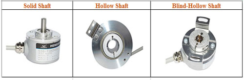
D. How to mount this encoder and how to connect the encoder to controls?
The encoder can be selected with a solid shaft, hollow shaft, or blind hollow shaft.
The hollow shaft and recess hollow shaft are quick and easy to mount.
But if there is movement or “run-out” in the shaft, the solid shaft with the appropriate coupling would be the better solution.
A coupling can have a radial offset of +/- 1.5 mm, an axial offset of +/- 1 mm, and can have an angular error of 5 degrees.
This may be enough flexibility to help prevent overloading the bearings of the encoder.
Shaft Type:
Cable Outlet Direction:
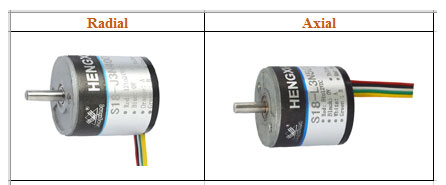
The encoders can be selected with cable or connector. If you choose the connector option, you will need a mating connector or a cordset (both connector and cable). This will give you a connection point to the encoder but does not necessarily get you all the way to your control cabinet. Depending on the distance, you may need a junction box, conduit, and cable tray. Care should be taken when routing encoder cable to reduce the influence of "noise". To reduce this influence, the cable should have a braided shield around the wires and the wires should be twisted pair. The encoder cable should be in a conduit with only low DCV cables and keep AC and high-power cables separated. If there are cable trays with AC and DC cables, there should be a grounded metal divider between the DC and AC cables. If the encoder cable does need to cross an AC cable, it should cross perpendicular (90 degrees to each other). The shield should be connected to one earth ground location in your control cabinet (so it has a star topology).
E What environmental and mechanical stresses does the encoder need to bear?
For the environmental aspects, the amount of moisture, duration of moisture, chemicals, and cleaning regimen need to be verified.
The IP50 rating is good for most applications with minimum moisture exposure, but if moisture is present for a longer duration, then you should select IP65 or IP67.
